FEATURE | The future of hydrofoils
The following is the presentation given at the fiftieth anniversary virtual symposium of the International Hydrofoil Society (IHS) by Professor Karl Gunter Wilhelm Hoppe – naval architect at the Technical University of Berlin, Emeritus Professor at Stellenbosch University in South Africa, and director at Foil Assisted Ship Technologies.
Hydrofoils are hybrids of a planing monohull with a foil system. Hydrofoils were developed over 100 years now with some high-tech applications in the 1960s and 1980s.
The fact that the IHS still exists means there is still strong public interest in hydrofoil development even though they are not anymore in the public news.
However, some of the later hydrofoils are still in operation in certain countries and especially the Russian river hydrofoils. And yet the talk still goes around that hydrofoils are “drying out” and becoming relics that belong in museums.
Inevitably, a question has arisen after so many years have passed without virtually any new hydrofoils being built: Did we run out of experts to design hydrofoils and build them?
The clear answer is no, as hydrofoil systems have strong applications in sailboats now with extremely high tech applications reaching over 50 knots in much slower winds.
However, these are mainly sport sailboats. Why then did the hydrofoils seem to disappear?
One has to look carefully at the design of hydrofoils to find out what the real reasons of their neglect could be and find out what restraints are involved as well as the associated costs.
The two photos below show examples of hydrofoils.

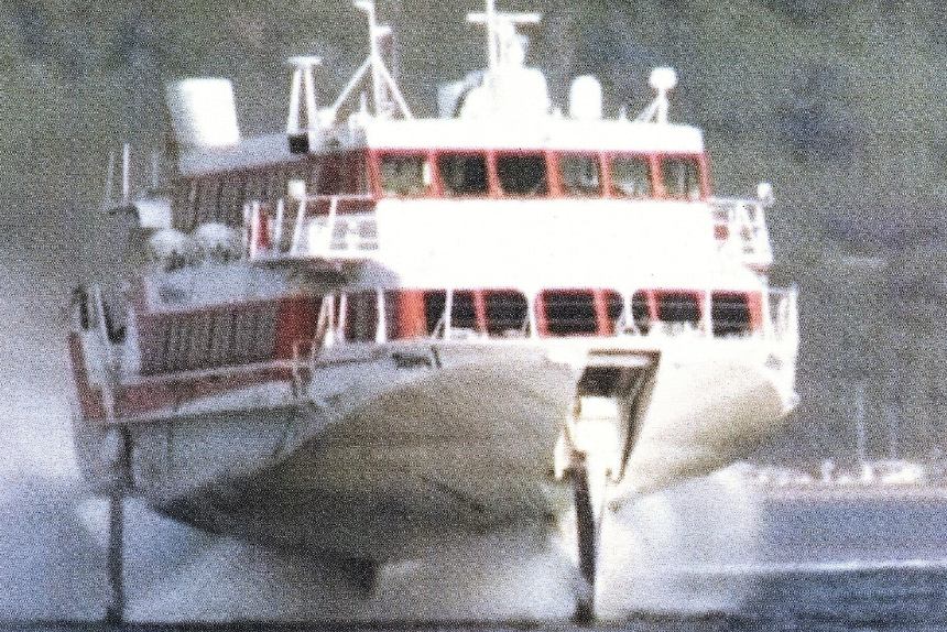
There are many different foil forms and combinations with monohulls.
There are V-shape foil systems, flat type foils and deeply submerged foils; mostly all foils come in pairs for longitudinal stability. The fundamental design concept behind all hydrofoils is the idea that the foil must carry the full load weight of the craft, driving the hull out of the water and letting the foil carry all the weight with the hull being carried as deadweight, which is only there to supply sufficient buoyancy at rest and low speed.
The request for safe stability complicates the hydrofoils and this led to various ways, either to have fixed foil systems with the V-foils piercing the surface or later developments with full submerged foils and angular automatic foil control which ended up in the Boeing hydrofoils’ high-tech wave scanning system as used in aircraft – which increases costs considerably.
Another design request concerns the operation in open sea waves to let the hydrofoil platforming, which means it is not following the wave surface contour but runs on a horizontal plane. This required the foils to be deeply submerged with long struts to transmit the full weight force into the hull, which is not supposed to have any water contact when the hydrofoil is “foilborne.”
These foils and struts were of solid high tensile steel and had to have polished surfaces as the foils lose efficiency when the surfaces are rough. In seawater, especially in warm, tropical areas, foils needed to be kept clean of fouling.
All these restraints led to expensive craft and high maintenance costs.
Propulsion systems are challenging with very long propeller shafts and low OPC data. To get the hydrofoil rising at start speed, considerable power is required before it becomes foilborne.
In very bad weather only very slow speed can be used with bad efficiency and bad sea-keeping due to the low deadrise of hull. Turbine and air propulsion have low efficiency.
Hydrofoil wings at very high speed have to be extremely slender with low thickness over chord to prevent cavitation. Such wings are highly stressed and bends and struts are required to carry the ship’s weight load.
These struts create additional resistance reducing craft efficiency. They also increase ship weight and costs.
Operational constraints
At speed, hydrofoils run high above the water. This increases their tendency to experience accidents when hitting floating objects. If these objects are solid like floating containers or floating trees, the hydrofoil will come to an abrupt standstill and crash into the sea with full power on.
Several fatalities were recorded in Hong Kong with the Boeing-type Hydrofoil ferries. Even the US Navy hydrofoil patrol boat USS Tucumcari had a serious accident wherein it struck a coral reef and ended up with some crewmembers sustaining serious – but non-life-threatening – injuries.
Hydrofoils require deep harbours and they cannot navigate in smaller harbors. They are not able to approach typical sandy beaches or land on one.
A Thai company had asked us to design a Hysucraft for beach landing as their Russian hydrofoil could not approach the beach to deliver passengers. The project did not materialise as local fishermen opposed the idea.
Hydrofoils, especially those used in defence applications, are easily detected by radar due to their higher profile compared to vessels with conventional hulls.
Hydrofoils also cannot manoeuvre alongside other ships because of protruding foils. Overland transport is complicated and special trailers are needed.
Yet with all these constraints, the classic hydrofoil vessels performed exceptionally well. In 1960 to 1980, craft efficiency had no high priority and power, fuel consumption and CO2 emissions were not yet taken seriously.
Today, with climate change and CO2 reduction requirements, the pressure is on ship designers to optimise hydrofoil vessel design to ensure operating efficiency and low fuel consumption.
Also, the use of electric drive systems requires low power as batteries are very heavy still and guarantee only short ranges.
Hysucraft
At the Stellenbosch University, RSA Marine Engineering courses were offered as early as the 1960s. The South African police and navy had requested assistance in the construction of fast patrol boats in the 10- to 15-metre range that could also operate at high speeds in extreme wind and wave conditions with short but very steep waves.
They had imported boats which did not function well and crews had to be retired already at age 40 because of damage to their kidneys and vertebrae.
We looked at offshore race boats and found that the so-called “tunnel boats” (actually split-deep-V-boats with a tunnel between two asymmetrical demi-hulls) performed best in rough sea conditions. Because of the high deadrise (24 degrees or more), they needed significantly greater engine power compared to monohull vessels.
I proposed to fit a single foil in the tunnel of such a boat at keel height to carry some of the ship’s weight more efficiently at speed. The idea was rejected. However, I tried to prove its usefulness and built a small model for towing tank tests.
Using a simple foil design with a good feel for size and profile (K-profiles) and with my experience on hydrofoil tests in the Berlin towing tank years before and also my experience on propeller design, the model was built and tested.
Expecting a 20 per cent resistance reduction, I was surprised by a 40 per cent resistance reduction. This was certainly a welcome development!
My research project at the university was called the Hysucat (hydrofoil-supported catamaran) Development, and many towing tank tests followed. Also, the theoretical development with software development for the design of Hysucat was started.
So, it was found out that the Hysucat mainfoil was considerably more efficient installed and that the interference effect increased the efficiency of hull and foil, as explained in the image below.
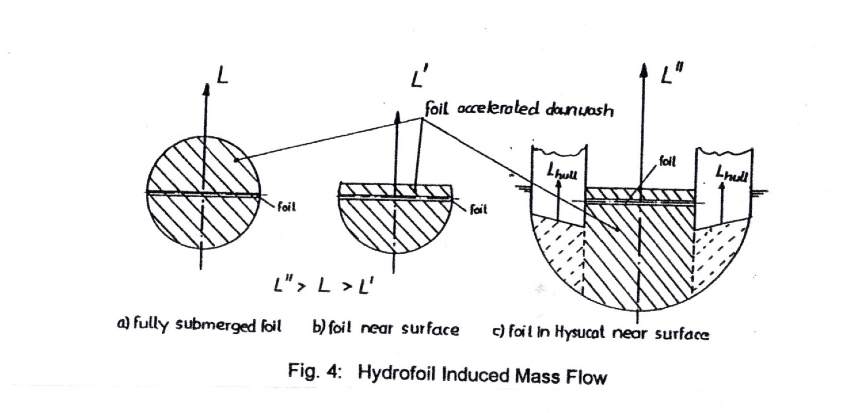
In the Hysucat arrangement the mainfoil is attached to the vertical tunnel walls and the foil has no tip vortex.
The foil induced downwash mass flow of hulls, and the foil is much larger than the downflow behind a free foil. The larger the induced downwash is, the more efficient the foil-hull combination will be.
This influence allowed the Hysucat to be considerably more efficient than originally expected.
Later we changed the name to Hysucraft (hydrofoil-supported craft) as we also developed foils for multihulls and even monohulls.
The fundamental design concept for Hysucraft was changed from “hydrofoils” in that the foils would only carry a partial load of the craft and relegate the stability reserves to the remaining portion of the hull that was in contact with the water surface.
So, there were no stability problems with our Hysucraft compared to “conventional” hydrofoils, wherein stability was a major problem. Hysucraft have none of the above design and operational constraints typical with hydrofoils. Further, the foils are smaller, lighter, and thinner – and therefore cheaper.
However, I want to mention two systems which give Hysucraft increased efficiency. The first are surface propeller systems with high OPC values. These propellers create strong uplift forces at the transom in the order of the thrust forces.
This has the effect as if the ship would be lighter which needs lower power. This uplift has to be incorporated in the trim calculations or it requires a certain LCG shift or foil shift.
The other propulsion system is a Servogear adjustable pitch propeller system which has a considerable higher OPC in the lower speed range as the pitch can be reduced for maximum propeller efficiency. This allows it to overcome the hump resistance at Froude number around 0.8 to 1.2 which is especially high when the Hysucraft is heavily loaded.
For extreme high speeds the propeller pitch is increased to deliver very high OPC values. Servogear systems also come with propeller half tunnels that create a significant uplift force, which in turn reduces apparent ship weight.
Hysucats can also be designed to land on sandy beaches and are easily transported on flatbed trailers.
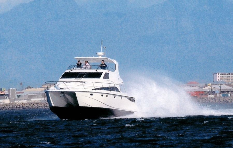
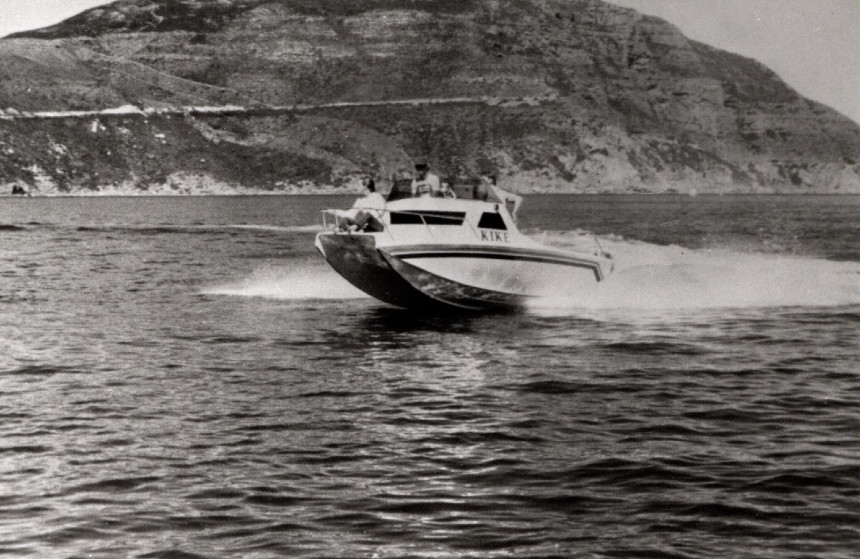
Please compare now the typical hydrofoils with our Hysucraft in the below image, which shows the first 5.6-metre Hysucraft on the water as a manned half-sized sea model.
You can hardly see the small mainfoil amidships and the twin rearfoils for trim stabilisation near the transom. This little boat performed exceptionally well even in extremely rough seas.
We gained the Shell design award for it, a first for Stellenbosch University at the time.
The BMI-Hysucat was tested for a whole year in the sea around the cape and many experts and vessel crews from the navy and private shipping companies were invited. They checked out the Hysucat’s performance even in wave conditions that no deep-V-hull vessel owners would dare to run with speed. This was in the 1980s.

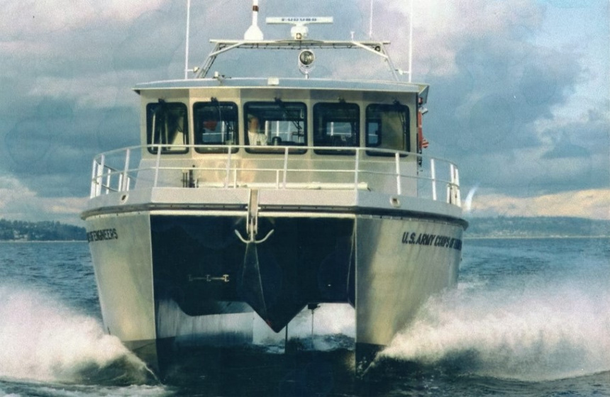
Many Hysucats were designed after this in South Africa first and soon after in Germany, Thailand, Australia, the USA, the UK, New Zealand, Brazil, Chile, Argentina, and Hong Kong among others. Including Hysucraft designs that are not our own, there must be several thousands of them on the water worldwide right now!


Ship evaluation method
During the Hysucraft development a tool was required to enable comparison of the ship’s efficiency with those of other craft. We already used a method to compare the quality of a foil wing with a planing craft by use of the aeronautical term lift/drag ratio.
In ship building the inverse is used to compare hull qualities, called the Resistance/Displacement ratio ε with R and D in Newtons it gives a dimensionless ratio.
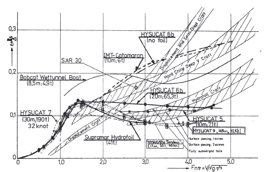
The ship weight is usually given in t = 1000 kg but as a force has to be in newtons: D [N] = D [t] * g [m/s²] with g being acceleration of earth, 9.81 [m/s²]. In Fig. 19 the Resistance over Displacement Ratio ε is shown and tendency curves of various types of ships indicated, including hydrofoils and Hysucraft which give best efficiency for fast craft.
However, to compare the whole ship’s or boat’s quality their propulsion power Pb [kW] has to be compared.
Pb is in the horizontal direction, whereas D is in a vertical direction and the basic Power:
Pbasic is D [N] * Vs [m/s] = Pbasic [kw]
A dimensionless ratio is achieved by the ratio of:
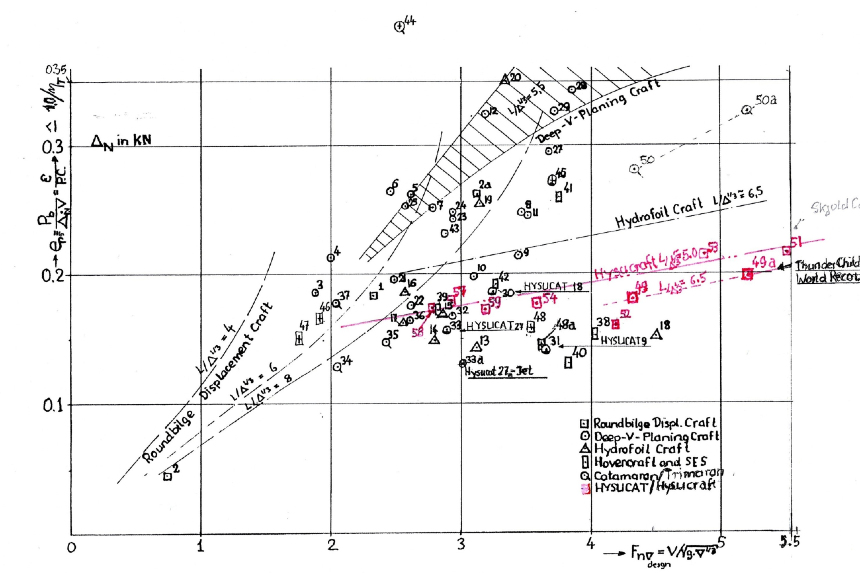
Pb / Pbasic = Pb / (D [N] * Vs [m/s]) = EPS which is the equivalent to R/D ratio but by comparison of Powers.
The EPS turned out to be the inversed of the well known Transport Efficiency.
The Froude Displacement number is FnD = Vs [m/s] / ![]() with ∇ [m³]
with ∇ [m³]
We determined the EPS ratios of many different ship and boat types and collected them and plotted them over the dimensionless ship speed, (the Froude Displacement number) in the second chart below, which also shows tendency curves of typical ship types. This gives a good idea how ships compare and for which speeds they are best suited.
We developed the hydrodynamic performance ratio (HPR) by dividing the Froude number by the EPS value, which is called HPR. The HPR indicates a ship’s quality by a single number. The largest number indicates a most efficient craft. The most efficient ships hardly reach a HPR of 30, which would be the most efficient craft seen.
The best hydrofoils reach about 22, USS Tucumcari about 18.3, some hovercraft about 26.3, SES Corsair about 22.54, the demonstrator craft Thunder Child II with 26.176 at top speed and 24.117 at 45 knots cruising speed, and the Alpha Yacht with 28.765 to name a few examples.
The above evaluation method gives every boat owner a tool to find out how well their ship compares to others.
Hydrofoils’ HPR data are somewhat disappointing as these might have been adversely influenced by the low OPC data of the propulsion system and by the often-used V-foils. It might have even impeded worldwide hydrofoil craft development. We thus see hydrofoils still used in certain countries but hardly any new developments in recent years.
More recently a Hysucraft hydrofoil system was designed for the 23-metre trimaran Thunder Child II of Safehaven Marine in Cork, Ireland in collaboration with Frank Kowalski.The foils improved Thunder Child II‘s performance by nearly 35 per cent.
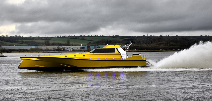
The World Speed Record Run for boats of 15 metres length or more was then established on August 9, 2020 on the Cork-Fastnet Rock-Cork route with average speed of 45 knots and 53 knots top speed. We are proud of this considerable result together with Frank Kowalski.
I hope that my contributions to the IHS project are well understood and that it dispells the notion of hydrofoils becoming obsolete. Hydrofoils will continue to be developed, maybe just in minor deviations from the traditional hydrofoil designs as the enormous lift-drag ratio of hulls with foils cannot be ignored in marine technology overall.
Already sailing boats are revolutionised by foil assistance and many smaller boats, especially those with electric propulsion systems, are showing improved performance.
I hope that the IHS will continue their valuable efforts and present the technological development of hydrofoil wings to improve popular understanding.
More great content as part of this month’s Hydrofoil Week right here.

